Tips for Working Effectively with Blend Curves
Some people use Blend Curves for every curve they create in Alias, some never use them at all, preferring the basic curves and the Align tool.
Blend Curves were primarily designed for ‘blending’, they default to a G2 (curvature) connection to a surface, and they are associative, sticking to the surface as it is moved or manipulated. So most users only use blend curves for creating transitions or blends between other curves and surfaces.
This tutorial presents a series of tips and techniques for using blend curves in this way. I am assuming that you have a basic familiarity with creating Blend curves, and using the blend curve edit manipulator to control their shape and continuity settings.
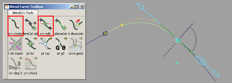
TIP 1: Two Golden Rules for using Blend Curves
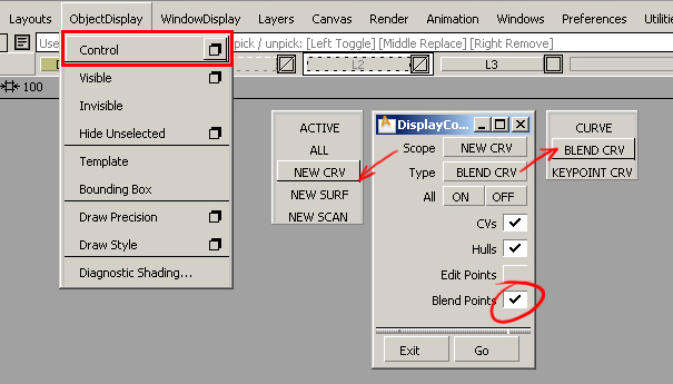
Golden Rule 1: Always display the CVs when using Blend Curves.
Underneath the clever blend curve interface is a normal NURBS curve. Everything that you already know about good curves applies equally to a blend curve. How can you see if the CVs and hulls are crossed over, uneven or zig-zagged if you haven’t looked at them?
You can change use the Object Display > Control settings to set blend curves to always have the CVs and hulls displayed when you create them:
Golden Rule 2: Always use the Curve Curvature plot to evaluate the character of the curve.
A blend should be ‘balanced’ with the peak curvature near the middle and each end doing an equal amount of work. Again, there is nothing magic about the blend curve, you need to apply all your judgement and control equally to a blend curve as to a normal curve.

TIP 2: Move the Blend Curve tools a Shelf and Customise
You can drag the Blend Curve Toolbox onto a shelf to ‘open up’ all the tools. This makes it easier to see what options you have available and let you weed out some of the tools you never use.
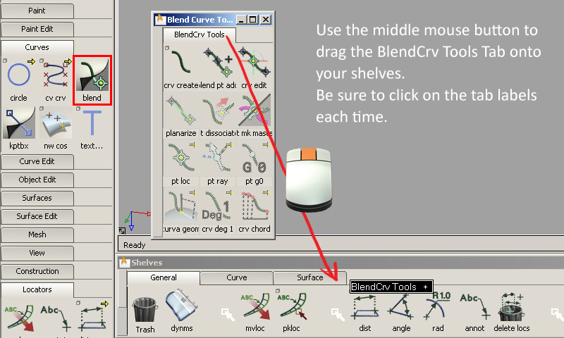
If you don’t have ‘Pick Blend Point’ on your marking menus, then you may want to add it to the shelf.

I also add the Curve Curvature tool, to remind me to use it, and I have re-named some tools using Alt+double-click. Finally I have used some Preferences > Interface > Shelf Extras to space out my tools.
TIP 3: Choose the Orientation of the Blend Curve Manipulator
When placing a blend point on a surface, the alignment directions available on the Manipulator will depend on where you initially place a blend point:
Placing the blend point on an isoparm or natural edge creates a manipulator with U and V alignment options:

Placing the blend point onto a trimmed edge aligns the manipulator to the edge direction:

TIP 4: Controlling Blend Point Direction
If two surfaces are close together, the blend curve will sometimes ‘flip’ in the wrong direction. The default manipulator shows two blue arrows, and these don’t allow you to flip the end of the curve.

Switching to the ‘single arrow’ manipulator allows you to change the direction:
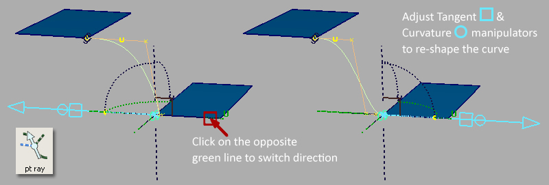
However it also changes the CV distribution along the curve, which you will need to adjust using the Tangent and Curvature manipulators. This is why I generally stick with the double-arrow default unless I have problems.
TIP 5: Using Auto Align at Corners
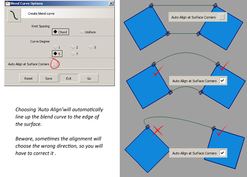
Open the Create Blend Curve option box to access the ‘Auto Align...’ option. This will attempt to automatically align the manipulator when you place a blend point at the corner of a surface. Mostly it works really well, but sometimes it can ‘guess’ wrong and align to the wrong direction. Always look at the flow of CVs to check the alignment.
TIP 6: Using Both Manipulators together to achieve a Balanced Curve
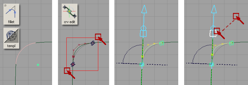
A common use of blend curves is to replace a fillet with a softer transition. Selecting both manipulators at once only displays one manipulator, but modifications to the tangent or curvature controls will affect both blend points equally:
TIP 7: Using Blend Curves to Design a Transition
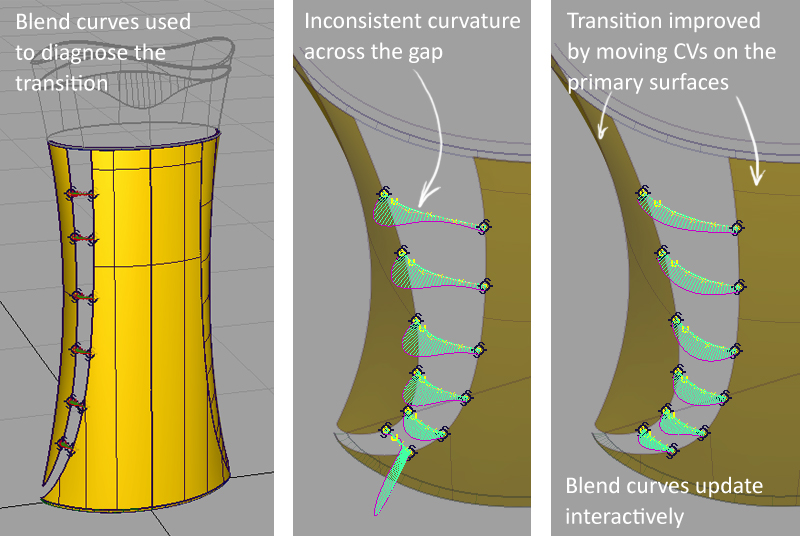
With this technique I’m not using the blend curves to build surfaces from, I’m using them as a diagnostic tool.
If I am having problem with a bi-rail surface giving me a bad result, the problem may be with how my primary surfaces are set up. Using natural blend curves (without modifying the manipulators) at many points along the transition area can provide valuable diagnostic information. I won’t use these curves to build from, I’ll just discard them once the problem is ironed out.
TIP 8: Using Blend Curves to accurately trace a Line
In this example, one end of a bi-rail can’t cross a split surface. One approach is to replace the two surface edges with a single line, and use that to create the bi-rail, (checking the surface continuity afterwards to see if it is acceptable).
Blend curves can be used to create a single curve that accurately matches a series of edges (or Curves-on-surface). Snap a new blend curve to evenly spaced locations, and make each blend point only G1 (tangency). Use the manipulator to align each blend point to the edge surface.
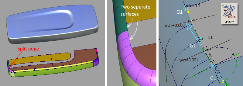
Use the Curve-to-Curve Deviation tool to measure the deviation of the curve, and move the blend points along the curve until you are within tolerance. Judging how many blend points will be needed will take some practice, but you’d be surprised how easy it is to reproduce a good quality curve that can be used for building accurately.
TIP 9: Don’t always use Blend Curves!
So, are blend curves always the best option to use? They are certainly efficient and I will use them for most blending situations. However, it is important to be able to use alternative methods for blending, particularly the Align tool, as there are some situations where Blend curves don’t always give the best results.
For example, if you want to have G2 continuity at one end and G0 at the other. You should only need a degree 3 curve with 4 CVs to achieve a good controllable result. However, choosing degree 3 for the blend curve results in a two span curve, giving one unnecessary CV.
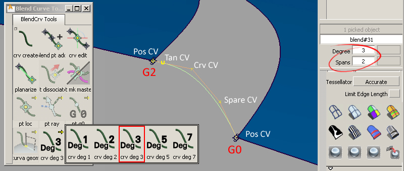
You can achieve a better, smoother result by creating your own curve with exactly the number of CVs you need, and using the Align tool to set up the continuity.
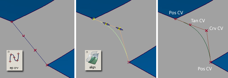
Many technical surfacers doing A-class modelling also prefer the direct control of the Align tool over the more indirect Blend curves.
Conclusion
Blend Curves are a useful, efficient tool and well worth becoming familiar with. But don’t forget the fundamental skills of having well-ordered CVs and evaluating your curves, as these are just as important for Blend Curves as for all the other geometry you create in Alias.
Kerry Kingston runs Bluesmith Ltd., an Alias Consultancy and Training company based in the UK.