
Introduction
For Class A work, your employer or client will typically have a company-standard set of Construction Tolerances. It's important that you find out what these are and to use them, (in which case you don't need to look at this checklist).
If however you are working independently and creating your own sets of tolerances, then guidelines for setting them up are given below.
Continuity Settings
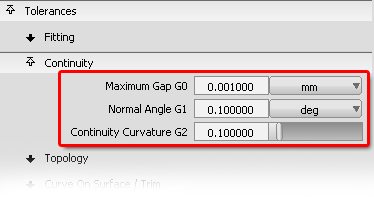
The three Continuity settings (G0, G1, G2) are the most important of all the Construction Tolerances, and should be the first ones you set.
These are fully explained in the Fundamentals Theory Builders, and recommendations are given for settings to use in different situations. The example shown here is typical for Class A production modelling:
 |
Theory Builder : Continuity 2 : Construction Tolerances |
Matching the Distance Tolerances
Recommendation : Match the four G0 Position tolerance values.
Having set the Maximum Gap G0 Continuity to your preferred value, then it makes sense to set the other three G0 settings to the same value:
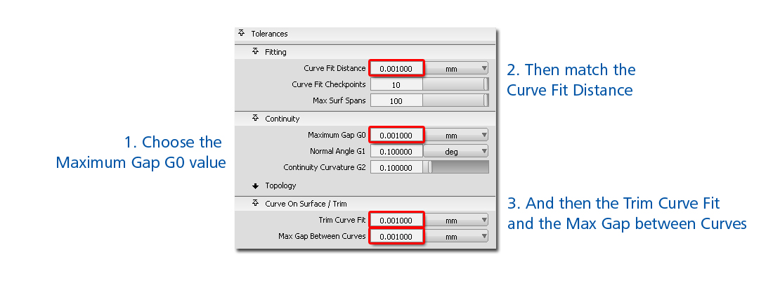
Note : Some users set the Curve Fit Distance and/or the Trim Curve Fit to an even tighter tolerance than the Maximum Gap G0 continuity. This will give tighter accuracy on those surface creation and modification tools that rely on these tolerances.
Checkpoints
Recommendation : Use the default value of 10. This is a reasonable compromise between:
- High enough number of checks per span to be confident that any deviation will be found.
- Low enough number of checks that surfaces are built quickly and a good user interaction speed maintained.
Whilst it is not recommended that you change this value, it can be one of the reasons why two surfaces may 'pass' continuity in Alias, and then 'fail' in another CAD system. If the other CAD system uses a different number of checkpoints, or an 'arc length' spacing instead of 'per span', then it may pick up a deviation that was missed in Alias.
Increasing this value will improve the accuracy at boundaries, but it will significantly increase calculation times and negatively impact the user-interaction speed.
Max Surf Spans
Recommendation : Use the default value of 100.
This sets an upper limit for surfaces built using tools such as Rail, Square, Fillet etc.
This setting is not particularly relevant for Class A surfacing, as it applies to multi-span surfaces (with the default setting, over 100 spans), which would not comply with Class A standards.
So the only practical use of this setting is when we create a poor set of criteria that would result in a heavy surface, the surface creation tool will 'give up' after it has reached 100 spans, so the user won't be left waiting for an impossible surface to try to be built.
Topology Distance
Recommendation : Always set to a looser value than the G0 Position tolerance, typically twice the value.
It is used by tools that work on a whole 'quilt', such as Offset, Model Check, Unify Normals. It's used to decide whether adjacent surfaces are to be considered as one surface quilt or as separate items. It is unrelated to checking for G0 Position Continuity for manufacture or data transfer integrity.
Setting this too close to the position tolerance will mean that too many surfaces will be deemed to be 'separate' when using these tools.
Setting up Site-wide Construction Presets
Your system administrator can create a custom preset that will appear in your list and can't be edited.
Refer to the Alias Help for details.