Advanced Sculpting
Too often we ‘force’ surfaces, shoehorn them into impossible corners and end up with wrinkly surfaces and failed continuity. Have you ever thought of ‘listening’ to your surfaces, contemplating your curves, and finding out what they have to tell you? Very often if we spend some time understanding how the NURBS material behaves, how it naturally wants to bend and blend, we end up with a much more successful result.
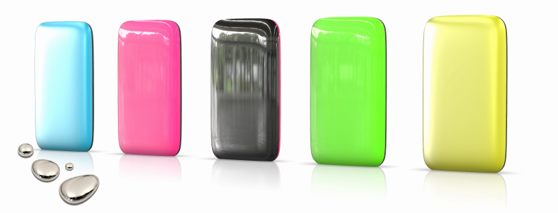
In this tutorial I look at modelling a soft, rounded back for a hand-held device (or the back of a flat-screen TV maybe). It wants to look like a drop of mercury, a smooth meniscus around the product.
First I will describe the typical modelling process, and then switch to a more exploratory method of modelling that starts to show us how to solve the sculptural problems.
Typical Modelling Process
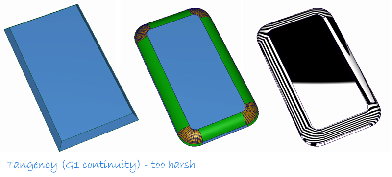
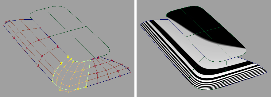
Building the surfaces with the Round tool gives a good hint as to the patch layout. But shading the model shows that we are a long way from the smooth, soft shape that we want.
The typical next step is to recreate the curves and surfaces using Curvature (g2) continuity instead of the Tangency (g1) given by the rounds, and by giving each blend surface more space to allow a smoother transition.
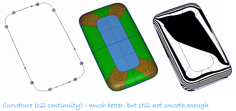
But we still don’t get the glossy, smooth effect we need when we check the reflections. So what are we doing wrong? Rather than give you a step-by-step ‘fix’, I’m going to describe techniques for exploring a solution to this problem, and show how the natural behaviour of NURBS surfaces and curves can help us achieve the subtlety that separates Alias surfacing from Engineering CAD systems.
Exploratory Modelling
I started by using two curves to explore what the back surface ‘wanted’ to be. A single curve has some tension, some resistance - it’s hard to ‘force’ the shape – instead I’m letting the curve tell me what shape is ‘natural’. Remember, this is the exploration phase, you won’t be using these curves for the final model, you are using them to understand how the form needs to work.
I tried to keep it as a single span,( going up to degree 9 if necessary), but when the back of the product is quite flat I may increase to 2 or more spans.

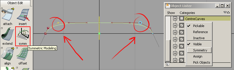
I’ll spend a lot of time on these curves, using the curvature plot to judge the character, and constraining the end tangents to create a consistent edge angle. I’ll deliberately use a single curve across the centre-line instead of a curve for half the product to ensure a very smooth surface across the middle. Before v2010 this approach has always been hard work as you need to be sure to pick the same CVs on either side each time you make an adjustment. And inevitably the sides get out of step! The new symmetric modelling tool in v2010 makes working symmetrically across the centre-line much easier.
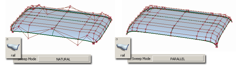
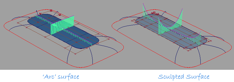
Then, I’ll do a simple mono-rail surface, exploring the Parallel and Natural options to see which will give me a regular CV layout.
I then trimmed the surface to the ground plane to compare the desired outline with the edge of the swept surface.
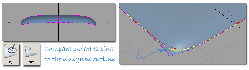
Shading shows that I have a very smooth surface, but one that doesn’t fit my designed outline. Massaging the CVs (again using symmetric modelling) gets me closer. I’m not worried that the edge is not perfect – this surface is for exploring the shape, not for the final model.
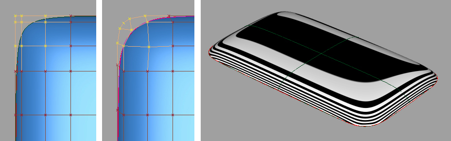
What I now have is a reference surface, one which gives me some idea how the blend should work around the soft corners. By exploiting the inherent smoothness of a single surface with few spans I’ve quickly achieved good highlights. The surface is usually good enough for presenting and evaluating the concept, and is quick to modify. But in this example I’m using it to better understand how to build a really smooth final model.
What have I learned from this surface?
The next stage will be to think about the patch layout for rebuilding the shape using surfaces which can be controlled accurately, particularly at the boundaries. The basic patch layout shown earlier is still valid, but choosing where to put the surface boundaries no longer needs to be guesswork.
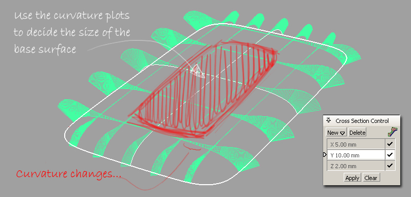
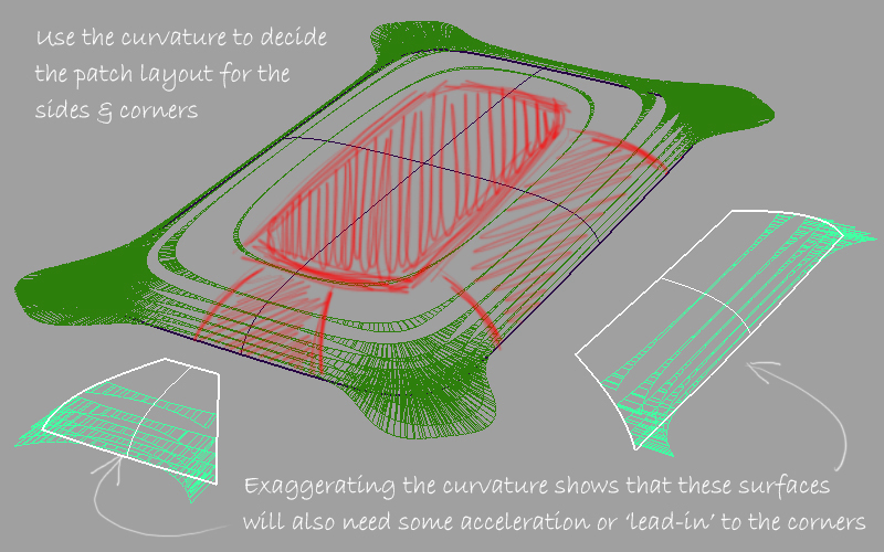
First, I used the curvature plots to evaluate the surface curvature. It’s clear where the surface changes from relatively flat to more sharply curved, so this is how I’ll define the boundary of the base surface.
To build this base surface I have two choices. Previously I would draw two arcs and use mono-rail to create a surface that I would then trim to the boundary. But if I just trim my sculpted surface and compare it I find a subtle, but interesting difference. Our sculpted surface has acceleration as it goes towards the edge, ‘leading in’ to the blends. This will give a much smoother result when creating the side surfaces at G2 continuity.
I used the ‘Shrink to Trim’ plug in to reduce the size of the large sculpted surface.
Looking at the z-axis sections lets me explore the layout for the side and corner surfaces. Again I am choosing the boundaries where the curvature changes from relatively flat to more sharply curved. If I experiment with trimming out the areas I’ve identified as patches, I can use the curvature plot at a larger scale to judge the character that will be needed for these surfaces when I finally build them.
Final Modelling
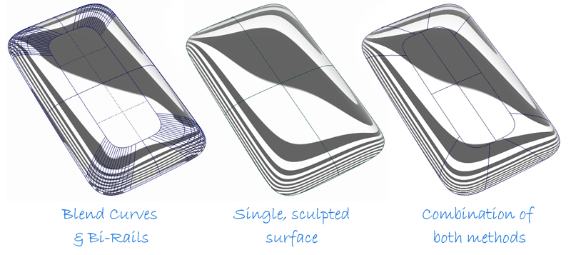
My single sculpted surface is my aspiration for smoothness, but it can’t give me the accuracy I need around the edge. Now, having learnt about the character that the patches of surface will need to create a smooth model, I will start to build it more accurately using bi-rail surfaces, or with direct modelling and CV sculpting. With each surface I will compare it to the ‘ideal’ sculpted surface and try to match the curvature plots and character.
Conclusion
Previous tutorials have discussed the importance of finding a good patch layout, and this can’t be emphasised enough as a key to producing successful surfaces. However, before patch layout you need to understand the shape you want to create and decide how to blend from one shape to another. Temporarily forgetting the need to achieve accurate continuity and just sculpting can give you valuable insight into how the surfaces ‘want’ to work.
Don’t be concerned if you build surfaces and then throw them away – the value is in what you learn about the 3D problem each time, not the actual surface. Remember, when you are concepting on paper, how many sketches end up in the bin?
The single NURBS surface is most like the natural ‘material’ of NURBS. If we work with it and become familiar with how it behaves in its ‘natural’ state we will spend less time fixing annoying technical problems and more time successfully solving sculptural challenges.
Kerry Kingston runs Bluesmith Ltd., an Alias Consultancy and Training company based in the UK.