Modelling Strategy
When I run training courses, one of the questions I’m constantly asked is how to do Modelling Strategy and Patch Layout. Sometimes you know every tool in Alias, but you still don’t know how to start on a complex model.
The problem is, it’s almost impossible to teach Modelling Strategy, as it is such a mix of experience, luck, talent and some ground rules. And it rarely gets taught in these neat tutorials on this site, because we teachers like to see everything work nicely, and we don’t like you to see that we also don’t know what we’re doing sometimes.
But I’m going to try to give you some of the ground rules that I apply when I’m working, and to let you see the messy , iterative process that makes for a real-life Modelling Strategy. This is very much a personal experience, so just try to get a flavour of the process rather than look at the detail of the models.
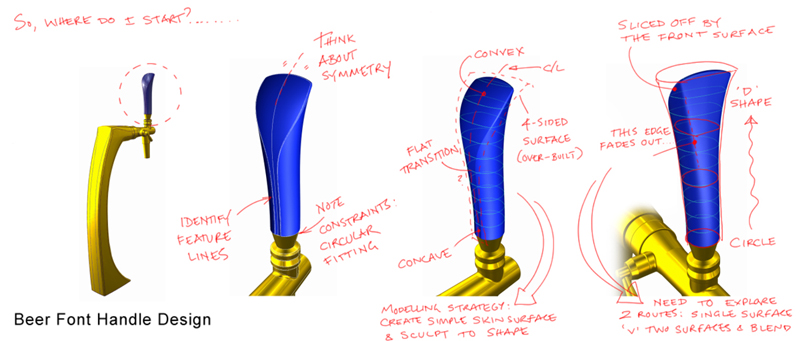
Here’s a simple example of a beer pump handle showing how it works for me. I’ll start with the basics :
Patch Layout Ground Rules:
- Always look for 4-sided surface patches.
- If there’s a 3 or many-sided patch, then you have to think about trimming a four-sided patch to get there.
Step 1 : Just get started in 3D
I start with the easy bits. Even if it’s just an outline block, or some underlay sketches. I’m always in a bit of a panic at the start of a complex job, thinking that I may not be able to model it, and so just getting started calms me down. I also find that starting to work in 3D space on the screen seems to kick off my 3D modelling brain, and I start to see how the surfaces could come together.
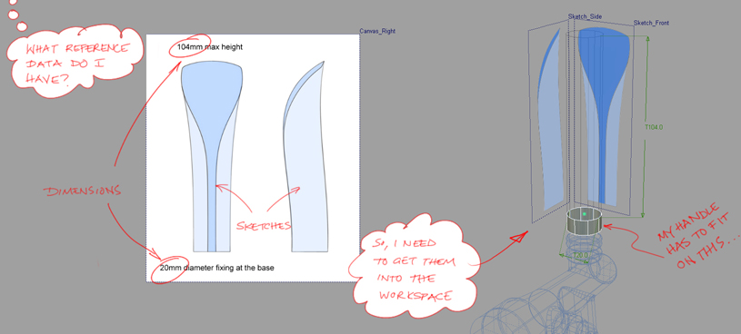
Then I start to try to guess what patch layout might work. Again, I look for the easy things : symmetry, feature lines, 4-sided patches.
Step 2 : Problem Solving
Then I start to experiment. I will work quickly and roughly, and what I am exploring is the patch layout. Its a problem-solving exercise, not really a sculpting one. All of the geometry that I create in the next few hours will probably get thrown away. And this is really important. One of the big mistakes that less experienced user make is to hang on to a piece of geometry and keep trying to make it work. Just because you’ve spent 3 hours trying to get a bi-rail to work, doesn’t mean you should spend another 3 hours failing some more. Throw it away and try a different approach (in fact you should have done that 2 hours ago).
I have a habit of direct modelling surfaces by sculpting CVs, but building curves and using surface tools is equally valid and more appropriate in many cases. Here I’ve quickly tested out my first guess at a modelling strategy:
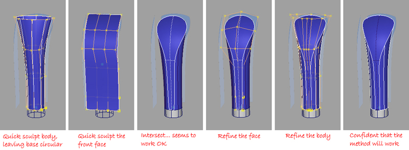
What I’m left with is an understanding of how the model will work as a patch layout, and some rough surfaces (which I’ll probably throw away). This 3D understanding shouldn’t be underestimated. After all, the design may go through many iterations before it is signed off. That understanding will be much more useful each time you have to re-build or modify your model than any particular surface.
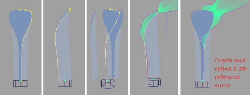
In the case of my handle, I learnt that the intersecting the two shapes gave me the design I wanted, but that it was tricky to get exactly the right intersection line just by pushing and pulling CVs. So I decided that I needed a 3D reference curve to help me get an accurate surface.
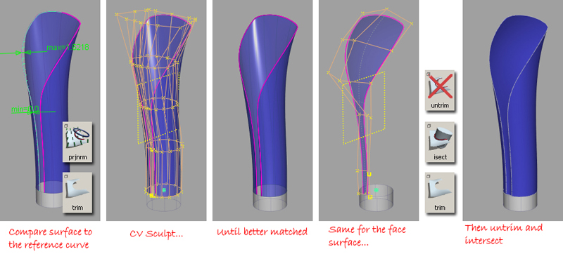
Step 3 : Sculpting
Now, I can start to craft my surfaces into the accurate shapes that I want. I will spend much longer on each curve and surface, as I now have a high level of confidence that they will be part of the final model.
For my handle, I worked on each surface separately, using the 3D curve to trim them rather than doing an intersection. I find this easier, as I only have one thing changing at a time. If I try to get the intersection right with two surfaces, then I’m never sure which one to change.
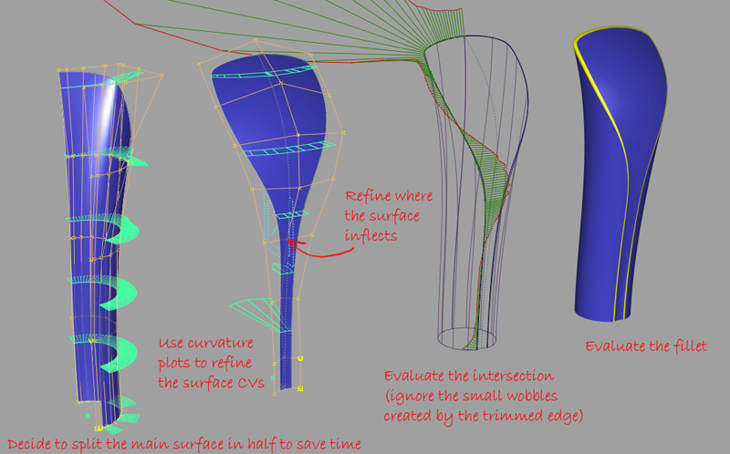
I start with as few CVs as possible in each surface, but I will typically increase the degree and/or the number of spans as I get closer to the final design.
Note that I like to work across the centre-line for as long as possible, so that I don’t need to worry about tangency. This is really just a personal preference, many people would work on one half only.
Is it really like that? Step 1, 2, 3 and then done?
No, of course not. I will bounce around between Step 2 and Step 3 many times. But I am always conscious of whether I am in ‘problem-solving mode’ or in ‘sculpting mode’
In ‘problem solving mode’ ...
- I work quite quickly, and don’t worry about perfect continuity or accuracy.
- I save very regularly, and with sequential filenames so that I can always go back to an earlier train of thought.
- I try alternatives, and save them.
- I hand sculpt surfaces to see how shapes might be solved.
- I sketch on paper (or on a canvas plane) to try out different patch layouts.
- I use all the Alias evaluation tools to try to get information on why a surface isn’t working.
- I expect to spend 70-80% of the job working in this mode.
In ‘sculpting mode’...
- I get much more organised with layers and naming.
- I work more carefully and accurately.
- I still save regularly and sequentially – If I go down the wrong road, I like to be able to re-trace my steps.
- I keep an eye out for ‘dead ends’. If I struggle with a surface for longer than 30 minutes, I go back to ‘problem-solving mode’ to try out alternative solutions.
- I enjoy it... I don’t spend much of the job in this mode, so I shade my model loads of times and admire how good its looking!
So here are some of my ‘flips’ between problem-solving and sculpting:
Here I’m taking time to refine the surfaces to try to get to a finished model.
Nearly there, but I don’t feel fully in control of the highlight at the back. So I switch to problem-solving mode and explore whether I should be splitting the rear surface into two, and using a fillet or blend surface.
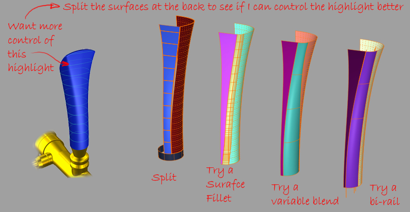
But actually, I discover that it’s more difficult to control, so I reject the idea – but I wouldn’t have known that if I hadn’t tried! So now I have more confidence that my patch layout is right, I just need to add some more CVs and spend more time sculpting and refining.
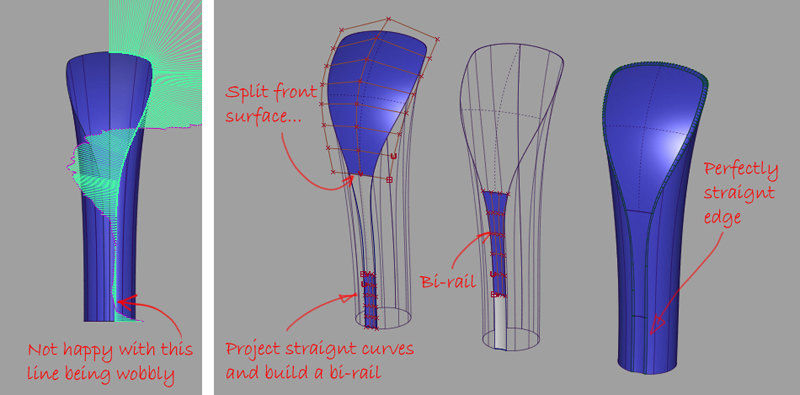
Finally, I’m not happy with the slight wobble at the front, so after a bit more problem solving, I end up with my final patch layout.
When you are designing by sketching on paper, how many sheets end up in the trash before you get the design you’re happy with? Feeling free to throw your Alias surfaces away and keep learning about the 3D problem you are solving is the same process. Even the most experienced Alias modeller often doesn’t know what patch layout to use, we just get quick at experimenting.
Kerry Kingston runs Bluesmith Ltd., an Alias Consultancy and Training company based in the UK.