Embossed Features – Lesson 3 : Geometry Mapping
To finish off the series on creating surface details, here is a short tutorial on the Geometry Mapping tool. This tool seems to have been around forever, but the interface can be confusing, causing many people to ignore it. Like the previous two methods, it is only used occasionally, but if you are aware of how it works, it will add to your armoury of weapons to tackle tricky modelling problems.
Unlike the other projection tools, this one is almost exclusively used for surface detailing. It’s used to ‘wrap’ curves around complex shapes and project them onto the surface. It’s particularly useful when the surfaces are too curved for a normal projection to work.
Understanding how Geometry Mapping works
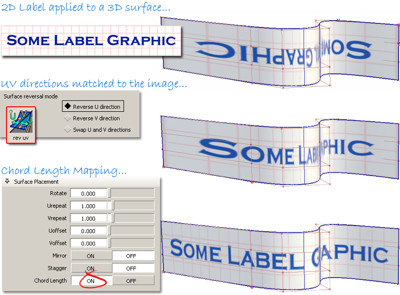
Geometry Mapping ‘wraps’ the curves (text for example) around the surface in exactly the same way as a texture map is applied during rendering. The texture map technique is illustrated below, along with some of the adjustments needed to get it working successfully.
The same processes are used to set up curves and surfaces for Geometry Mapping, but the interface and options used are different.
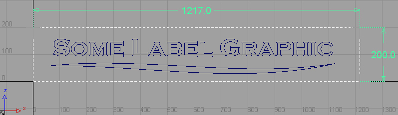
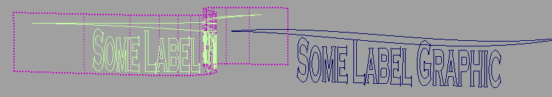
First, set up the Label ‘graphic’. Instead of creating a JPG or TIF image, you will create curves in one of the orthographic windows. It doesn’t matter which window you use, as long as you note whether it is the XY, the YZ or the XZ window. In the illustration below, white dotted lines are shown to indicate the size of the ‘label’ that you want. Although you don’t need to create the white lines, you do need to have an idea of the ‘label’ dimensions, as these will map directly to the UV dimensions of the surface. (Turning the grid numbering on will help to visualise an imaginary label area.)
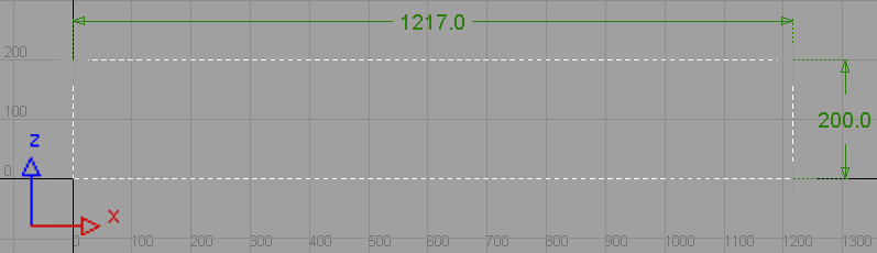
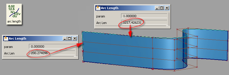
If you want to be precise with the size, you can measure the edge of your surface with the Arc length tool, and make the ‘label a proportional size.
Then, place your curves or text curves within this box. Position them so that they relate to the box in the same way as they will be positioned relative to the surface. You can’t be very exact about this, but don’t worry, as you can adjust the position later using construction history.
Now you’re ready to map the curves onto your surface.
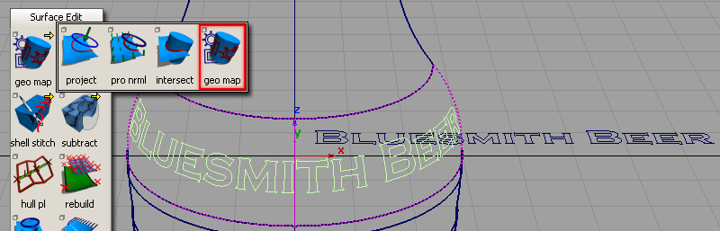
Start by double-clicking on the Geometry Mapping icon to open the option window and set up the mapping. I find it easier to work out the right setting first, and then ‘Save’ the settings in the option window. Then, I’ll select the surface, and click on tool to actually make the projection.
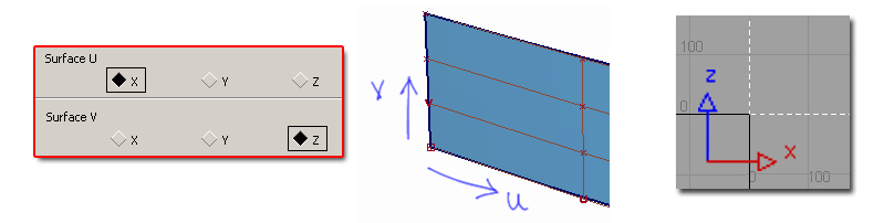
In the first section, specify which two of the x,y,z axes you have created the curves in, and relate these to the U and V direction on the surface. (You may choose to change the UV directions on the surface to better match the graphic, using Surface Edit > Reverse Surface UV.)
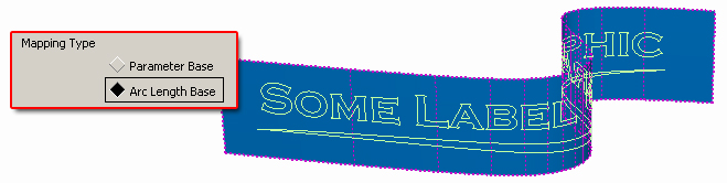
In the second section, choose the ‘Arc Length’ option to minimise the distortion across the surface isoparms.
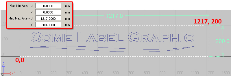
In the third section, specify the co-ordinates of the imagined ‘label’ area.
To execute the projection, first select the surface, and then click on the Geometry Mapping tool (or double-click to open the option window). You are prompted to select the curves. Unfortunately there is no way of using a drag box to select many curves at once, you’ll have to select them one-by-one.
If the result is not exactly as you want it, you can make us of construction history and modify your curves, the trim curves on the surface will update.
Examples of Geometry Mapping
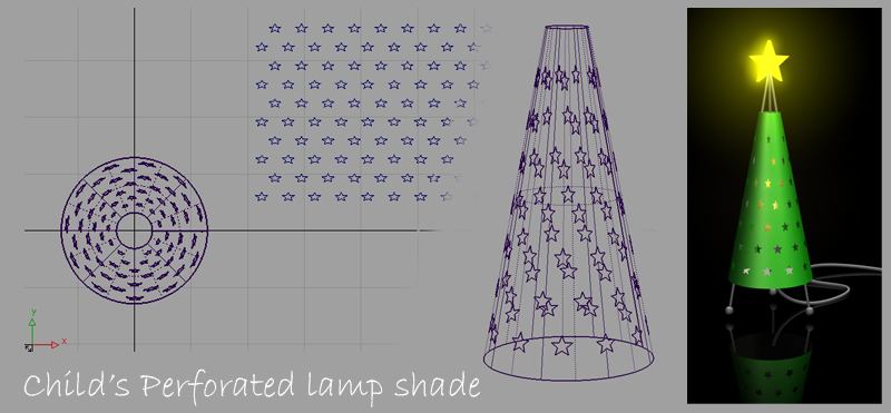
In this example of a novelty lamp, an array of shapes are projected around the shade and trimmed out to create holes. Construction History is used to move, scale and rotate the star shapes until a pleasing perforated design is achieved.
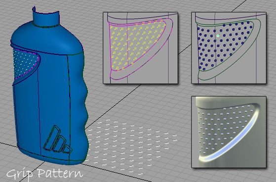
Classic grip patterns around areas that need to be handled can be created using Geometry mapping. Here, I used an array of simple lines, and used them to snap small spheres into position. Intersecting and trimming (or Booleans) creates the final shape.
Returning to the example used in the first tutorial, Geometry Mapping can solve the issue with distortion over conical or curved surfaces:
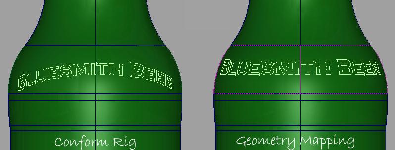
Particularly with Logo graphics, even a small distortion is usually unacceptable to the marketing department. So, even if the surface is only gently curved, compare the results with normal projection and Geometry Mapping, and choose the most accurate method.
Kerry Kingston runs Bluesmith Ltd., an Alias Consultancy and Training company based in the UK.