Embossed Features – Lesson 2 : Displacement Mapping
In the last tutorial, we built NURBS surfaces for embossed lettering on a beer bottle. This time we’ll use Displacement Mapping to create a polygon model suitable for rapid prototyping or rendering.
Usually Displacement Mapping is a rendering ‘trick’ to give a surface a complex look without having to model it. However, we can also use this technique to create a real model – a polygon (mesh) - which is a good enough for prototyping and design development.
In this tutorial we’ll create a logo graphic (as .jpg or .tif), and use it as a displacement map to emboss a logo onto the shoulder surface of a beer bottle.
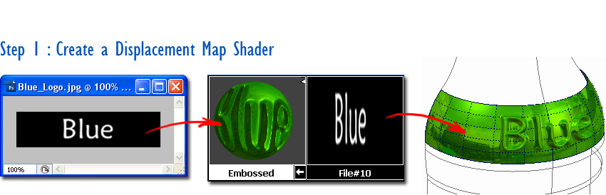
Start by creating a shader with a displacement map and applying it to your surface. Use black for areas that won’t be displaced, and white (or shades of grey) to specify the displaced areas.
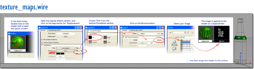
For anyone who is unfamiliar with setting up texture maps, a wire file is provided with instructions for both surface and solid mapping : texture_maps.wire. Also, Chris Hisey gives a good introduction on how to set up a displacement map in the ‘AliasStudio Displacement’ tutorial posted June 15, 2008. Have a look at this first if you are new to using the rendering tools for texture mapping.
Typically the logo area will require lots of polygons to display the intricate shape, whereas the rest of the model will need less, as the curvature will be less extreme. It makes sense therefore to isolate the area needed for the logo into a small, separate surface.
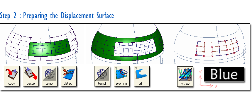
In this example, I made a copy of the surface so I could create one small surface (for the logo), and another larger surface (for the non-displaced parts). For the logo surface, I used Object Edit > Detach (or Extend) to cut it down to the area I wanted for the lettering. I didn’t use trimming because the texture map would have still stretched across the whole untrimmed surface.
I then used Project Normal and Trim to create the ‘hole’ in the main surface.
I also modified the UV directions of the logo surface so that the texture map would orient correctly first time. Use Surface Edit > Reverse Surface UV and open the option window to choose how to organise the U and V directions.
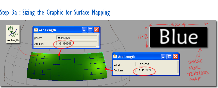
The graphics will be easier to place accurately and without distortion if the image proportions match the surface. To do this, I measured the edges of the surface using the Locators > Arc Length tool, and then sized my displacement image to roughly the same proportions.

If the surface is unevenly parameterised, you can choose the Chord length option in File Texture option window to map more accurately.
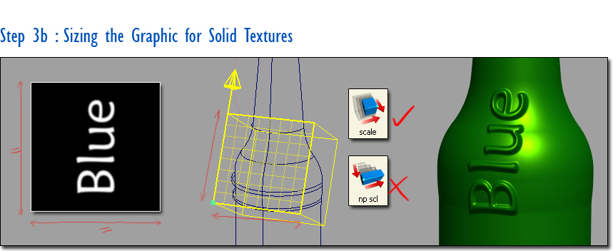
If you’re using solid projection, create your image as a square, so that it will map exactly to the texture placement icon without scaling. This helps to keep your logo in proportion as you’ll only need to Transform > Scale the placement icon and avoid using Non-P Scale.
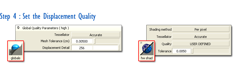
The number of polygons used to create the embossed shape is set up in the Render > Globals option box. Set the Displacement Detail to 256 or 512 to see a reasonably detailed result.
You’ll need to use rendering to preview the displacement quality. If you are viewing the model using Hardware Shade, set the quality to User Defined with a tight tolerance to view the displacement accurately enough. Alternatively use Render > Direct Render.
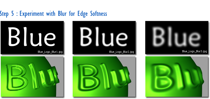
Embossing in glass gives a soft, undefined edge. The easiest way to set up the blurred edge is to soften the edges of your displacement image using the Gaussian Blur option in Photoshop. You will need to experiment with this a few times to get the effect you want.
If you can’t create the blurred effect in your graphics software, you can try using the BlurMult setting in the File options, but the results will be less refined.
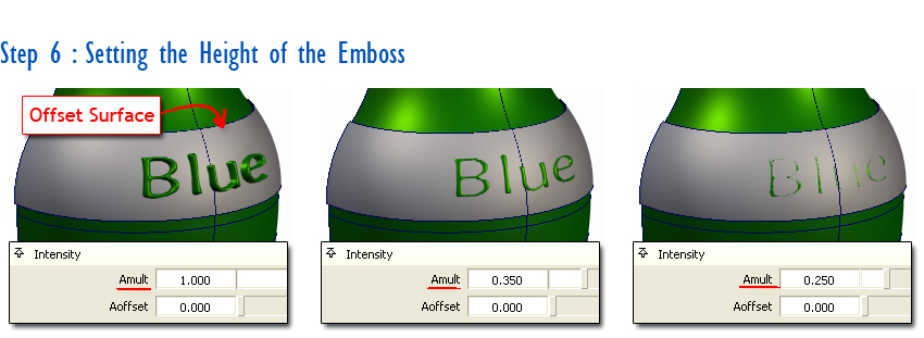
The height of offset is set by the Amult value in the File Texture option window, but it is tricky to relate the value typed in to the actual depth on the model. To get a more accurate offset value, create an offset surface at the height you want (say 0.5mm) to use as a reference. Then iterate the Amult value until the emboss just disappears under the reference surface. Then discard the reference surface.
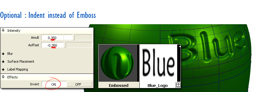
To create a de-boss or indent, first invert the image (using the Effects section of the File Texture option window), then set the Aoffset to a minus value to compensate for the white background displacing. If you mirror the values for Amult and Affset you should get a smooth result.
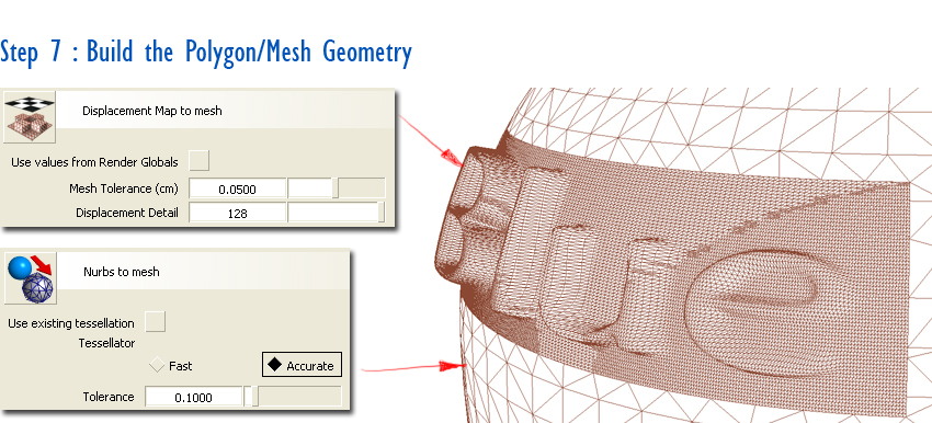
Once you have a rendered view that you like you can then create the polygon geometry. I used two different techniques for the logo surface and all the main bottle surfaces:
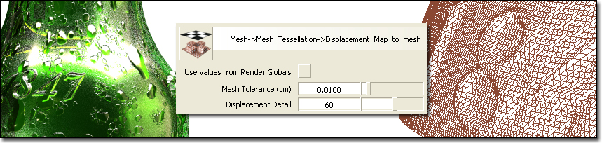
1.For the logo surface I used Mesh Tessellation > Displacement map to Mesh. Open the option box and select a high Displacement detail (the range is 10 to 512, you can type a higher number than 100). Experiment until the mesh is detailed enough to represent your embossed shape well. Alternatively, select Use Values from Render Globals to use the settings you used for rendering.
2.For the main surfaces I used Mesh Tessellation > NURBS to Mesh. Again vary the option box settings until you get an accurate enough result.

Use Mesh > Mesh Partitioning > Mesh merge - to group all the polysets into one.
Because the two meshes were created with different tolerances, there will inevitably be some small gaps between them. This may not matter – your model maker may be able to zip up the gap easily. But if you want to have a coherent poly model, you will need to close the gaps yourself. If you have Autostudio, you can use Mesh > Mesh Stitch- to stitch together the open edges.
Finally, use File > Export > STL to export the polygons in rapid prototyping format.
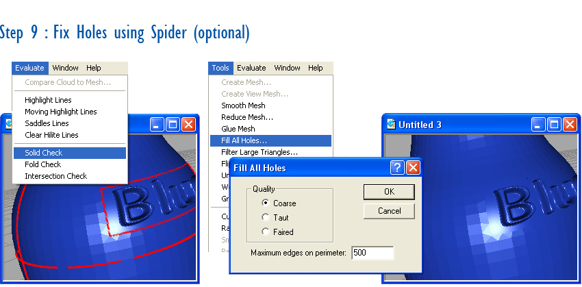
The easiest way to fix any holes in the STL file is to use the Spider software. However, Spider was only shipped with older versions of the software, and then only with AutoStudio and SurfaceStudio. If you do have Spider, open up the STL file and use:
Evaluate > Solid Check – to see if you have any holes
Conclusion
Tools > Fill All Holes – to fix the gaps. You may need to increase the Maximum Edges... setting to fix long edges.
This is not a technique that you’ll use often, but when you have a complex decoration on a package or a product, it can give you a great result with minimum effort. But remember, you’ll only ever get a polygon model from it, so if you need a more accurate NURBS model, use the techniques described in the previous and the next tutorial.
Download Data Files : BeerBottle.wire
Kerry Kingston runs Bluesmith Ltd., an Alias Consultancy and Training company based in the UK.